Pod Base

Ever have one of those projects that when you started it you paused and thought:

“Just what was I thinking?!”

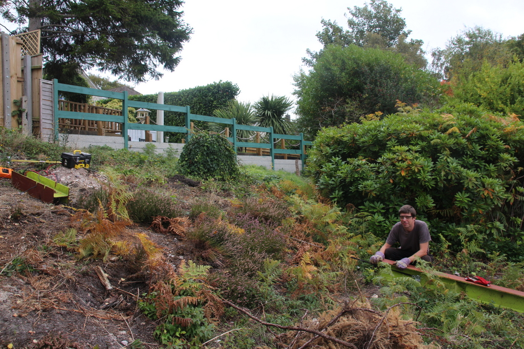
My wife and I chose the house that we bought primarily for its outside space. In addition to being able to have an interesting garden there was a spot in the top corner with a great view for me to build myself a longed wished-for outbuilding for my hobbies and interests.

The site for the outbuilding (“The Pod”) has a bit of a slope, and my first intention was to level the ground by excavating the upper part of the slope, and using the earth to build up the lower part. After discussing my plans with the local planning office they told me that that constituted “Engineering Works”, and would require a planning application at a cost of over £200. I proposed that I just raise the the front of the building on supports, and was told that because I wasn’t changing the level of the ground, and that the height of the building was measured from the highest part of the ground then it would fall under “Permitted Development”, and I could just get on with it.

What to support the Pod on then? Reclaimed railway sleepers – too uneven. Concrete blocks – I’m not so good at brick and block work. I found someone online that had two RSJs (Rolled Steel Joists / I-Beams) for sale. It was probably over-engineering the problem, but at least it would do the job.

Then they turned up.

RSJs

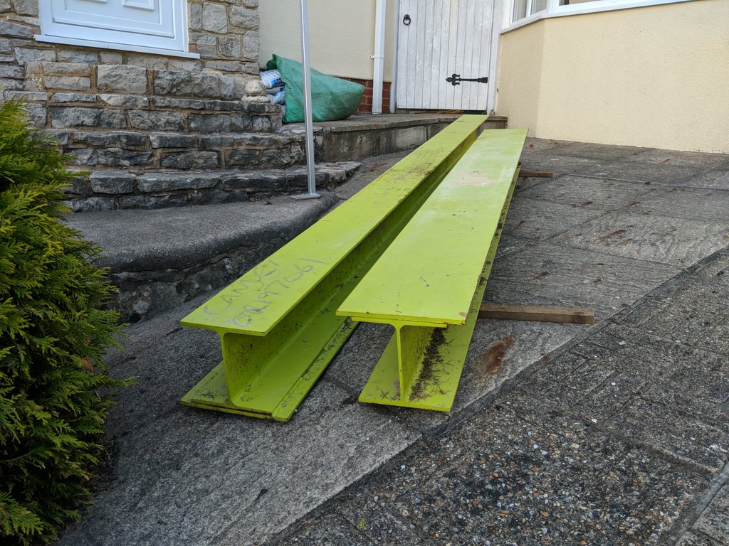
They were delivered by a team of 4 men, and with my help we barely got them off the back of the truck without breaking the paving slabs in my drive. They told me that the only reason they were selling them is that they’d underestimated the weight of them, and couldn’t actually install them. And now I had to somehow move them up the garden by myself.

They sat on the front drive for several weeks…

Ignoring them didn’t seem to move the project forward, neither did staring at them. They had to be moved, which meant that they had to get lighter, which meant they had to be cut down. My 115mm angle grinder simply wasn’t going to to be up to it, so I purchased up upgrade from Screwfix; a 230mm type.

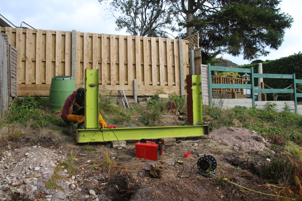
I donned the correct PPE; face shield, gloves, safety glasses, etc., and with my wife’s words of encouragement (“BE BLOODY CAREFUL!”) I set to work. When cut down the largest piece was still too heavy to carry; it would only move a few centimetres every time I shoved my whole weight against it. It would literally take all day moving it like that…

Yup, a whole working day later the beam was nearly at the top of the garden. I had to borrow an electric winch for the last few metres.

Moving RSJ with winch
Moving the RSJ the last few metres with a winch

The matter of welding the beams to form the support was far less strenuous.

Welding the RSJs
Welding the RSJs to form the front support
The finished base
The completed base

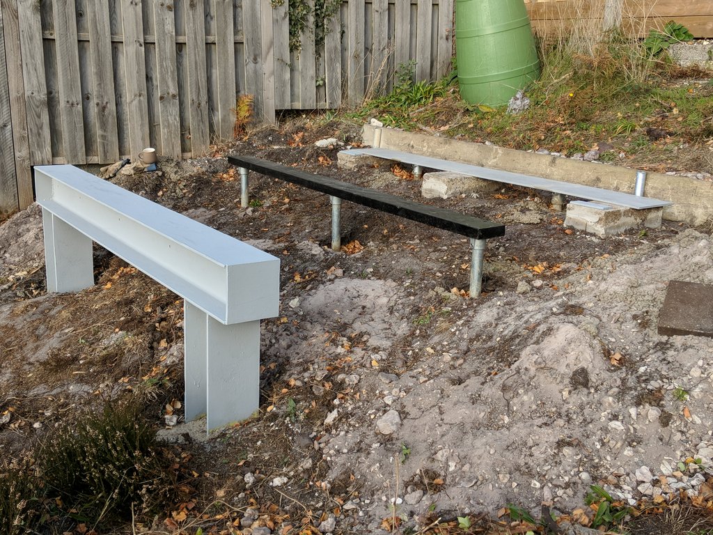
I asked my someone who has a lot more experience of building that I do whether he thought that the base would be strong enough.

“What are you going to put on it, a bloody skyscraper?!”.

Over-engineered, but not going anywhere, then.

Spring-Damper

\(\renewcommand{\vec}[1]{\mathbf{#1}}\)
This work is the result of part of a project I undertook in the early 1990s to devise software that would let me “paint a machine” onto my computer screen and then see it working. It was based on a system of particles connected with rods with various optional devices attached (rocket motors, wheels, parachutes, etc.), and was implemented on an Amiga 1200.


Imagine there are two particles \(\vec{p}_1\) and \(\vec{p}_2\) moving with velocities \(\vec{v}_1\) and \(\vec{v}_2\) respectively. They are connected by a spring of stiffness \(k\) and natural length \(n\), and a damper of resistance \(r\).

Spring-Damper

We’re only dealing with 2 dimensions at the moment, so we convert the vectors to their Cartesian components thus:

\(\vec{p}_1=[p_{x_1},p_{y_1}]\)
\(\vec{p}_2=[p_{x_2},p_{y_2}]\)
\(\vec{v}_1=[v_{x_1},v_{y_1}]\)
\(\vec{v}_2=[v_{x_2},v_{y_2}]\)

\(p_x=p_{x_1}-p_{x_2}\)
\(p_y=p_{y_1}-p_{y_2}\)
\(v_x=v_{x_1}-v_{x_2}\)
\(v_y=v_{y_1}-v_{y_2}\)

Spring Force

The force on the particles caused by the spring is equal to the difference in the spring’s natural length and its deformed length, divided by the natural length, all multiplied by the spring stiffness:

\(f_{spring}=k\frac{\sqrt{p_x^2+p_y^2}-n}{n}\)


(we have defined the the force to be positive when the spring is in tension, and negative when in compression)

Damper Force

The force caused by the damper is a little more complex to calculate. It is equal to the rate of change of the length of the damper times the damper resistance.

First, we find the length of the damper, \(d\), as a function of time, \(t\):

\(d(t)=\sqrt{(p_x+v_xt)^2+(p_y+v_yt)^2}\)


This expands to:

\(d(t)=((p_x^2+p_y^2)+2(p_xv_x+p_yv_y)t+(v_x^2+v_y^2)t^2)^\frac{1}{2}\)


Next, we differentiate with respect to \(t\) to find the rate of change:

\(d'(t)=\frac{1}{2}((p_x^2+p_y^2)+2(p_xv_x+p_yv_y)t+(v_x^2+v_y^2)t^2)^{-\frac{1}{2}}(2(p_xv_x+p_yv_y)+2(v_x^2+v_y^2)t)\)


Since we are only interested in the force at one instance in time we can evaluate at \(t=0\):

\(d'(0)=\frac{1}{2}(p_x^2+p_y^2)^{-\frac{1}{2}}(2(p_xv_x+p_yv_y))\)


which simplifies to:

\(d'(0)=\frac{p_xv_x+p_yv_y}{\sqrt{p_x^2+p_y^2}}\)


multiply by the damper resistance to get the force:

\(f_{damper}=r\frac{p_xv_x+p_yv_y}{\sqrt{p_x^2+p_y^2}}\)


(we have defined the force to be positive when the damper is expanding, and negative when compressing)

In 3 dimensions?

Ok, but what about in today’s miracle age of 3D, VR, jetpacks, and AR? Well, if you go through the above in 3 dimensions then you get the following:

\(f_{spring}=k\frac{\sqrt{p_x^2+p_y^2+p_z^2}-n}{n}\)


\(f_{damper}=r\frac{p_xv_x+p_yv_y+p_zv_z}{\sqrt{p_x^2+p_y^2+p_z^2}}\)

In vector notation

Just in case you want to do the calculations in 4 dimensions (Marty), or more, then these are the equations in general vector notation:

\(\vec{p}=\vec{p_1}-\vec{p_2}\)
\(\vec{v}=\vec{v_1}-\vec{v_2}\)

\(f_{spring}=k\frac{|\vec{p}|-n}{n}\)


\(f_{damper}=r\frac{\vec{p}\cdot\vec{v}}{|\vec{p}|}\)

Demo

Ok, there is no demo at the moment. I’ll get round to writing something in JavaScript or Unity “real soon now”

Automatic Pinout Diagrams

One of the more tedious aspects of documenting designs is having to produce pinout diagrams for microcontrollers. The two methods of doing this are a) draw it from scratch in Photoshop, or b) load an existing pinout into Photoshop, wipe the details so you can include your own.

To cut a long story short I wrote a PHP library to render a pinout diagram from a device definition file. By way of an example, the following device definition json file:

{
	"name": "Serial Infrared Decoder",
	"description": "Serial Infrared Decoder based on PIC12F675 8-Bit Microcontroller",
	"package-type": "SDIP",
	"pin-count": 8,
	"pinout": {
	    "undefined": "NC",
		"pins": {
			"1": {
				"name": "VDD",
				"signal-direction": "none",
				"description": "Positive supply"
			},
			"2": {
				"name": "IR IN",
				"signal-direction": "in",
				"description": "Infrared module input"
	                },
			"3": {
				"name": "IR IN",
				"signal-direction": "in",
				"description": "Infrared module input"
                        },
			"4": [
					{
						"name": "MCLR",
						"inverted": true,
						"signal-direction": "in",
						"description": "Master clear"
					},
					{
						"name": "VPP",
						"signal-direction": "in",
						"description": "Programming voltage"
					}
			],
			"5": {
				"name": "Serial Out",
				"signal-direction": "both",
				"description": "Serial data output"
	                },
			"8": {
				"name": "VSS",
				"signal-direction": "none",
				"description": "Ground reference"
			}
		}
	}
}

…produces the following output:

I’ve made the code open source available on github. It’s also available as a Composer package on Packagist.

Infrared Remote Control

Infrared remote control is considered a bit quaint these days – radio frequency modules are now readily available that offer long range, easy interfacing, and low cost. Why create an IR system, then? Apart from having a very particular application in mind (more on this in the coming months), it was a good intellectual exercise that gave me some experience with the interrupt and timer features of the PICMicro microcontrollers.

Principle

At its most basic level, infrared (IR) remote control works by a transmitter emitting pulse infrared light that is then detected by a receiver. The frequency the IR is pulsed at is called the carrier frequency, and is usually between 30KHz and 56KHz (38KHz is very common). Most systems work by sending data that is encoded into the spaces between short bursts of the pulsed IR light. These short bursts are known as marks.

IR Marks and Spaces

Protocol

The protocol I’ve devised is much like many of protocols used in remote controls.

First, 2 ‘leader’ spaces of 932µs are sent to denote the start of a valid signal. The bits are then sent (starting with the least significant bit (LSB)) as 8 spaces; a 0 represented by as 580µs space, and a 1 represented by a 756µs space. A compliment of the byte is then sent for error detection.

IR Encoding Scheme

Hardware

Transmitting IR is simply a case of modulating the output of an IR LED. For short ranges the LED can be driven directly from a microcontroller, for longer ranges the LED can be driven with higher current via a transistor.

To receive the IR signal the receiver has to be able to detect the pulsing of the light at its carrier frequency. Fortunately, there are easy to use modules to achieve this. I’ve been using the Vishay TSOP1840 module; a 3 pin device that pulls an output pin low whenever IR at the carrier frequency is detected (the TSOP1840 is quite old, and has undoubtedly been superseded by newer devices). The TSOP1840 is optimised to detect a 40KHz carrier, but it will detect a 38KHz carrier albeit with reduced sensitivity.

Reference Implementation

The reference implementation for both receiving and transmitting uses a PIC16F628A microcontroller coded in assembler. Pinouts, circuits and links to code below:

Transmitter Reference Implementation

IR Transmitter Test Circuit

Receiver Reference Implementation

IR Receiver Test Circuit

Source code on Github (GNU GPLv3 Licence).

This implementation is a Reference Implementation, which means exactly that – it’s not supposed to be deployed as-is, but to be the basis of a more featured system. I have, for example, modified the transmitter implementation to read the keyboard matrix of an old Atari Jaguar controller which I can now use a generic controller for future projects.

Comms Cabinet Controller/Monitor

This project was a real “Parts-bin Special”; made up from a load of stuff I’ve had hanging around at the bottom of boxes for years. What it does is pretty useful to me, though.

Last year I networked my entire house with a gigabit LAN. CAT6A cable runs from RJ45 sockets all over the house up to the loft where they are terminated at a patch-panel in a 6U 19 inch rack-mount cabinet. This cabinet houses a 24-port switch, router, cable-modem, and a server (an Intel i5 with 8GB of RAM in a 2U case, in case you’re interested). For a few days last year the sun did actually shine on my house, and subsequently the temperature in the loft rose alarmingly quickly. The power led on the cable-modem changed from blue to pink – a quick visit to Google confirmed that it was getting too hot. My quick fix consisted of running a couple of old CPU fans over the modem and router, and removing the door and side-panels of the cabinet. It worked, but was hardly a long-term solution.

There was nothing for it but to break-out the power-tools, and cut holes in the cabinet to permanently fit some fans.

Cabinet Fans
Cabinet Fans

All well-and-good, but how to control the fans? I was glad to finally find a use for the following stuff that I’d probably bought for various long-forgotten projects!:

Cabinet Controller/Monitor Circuit
Cabinet Controller/Monitor Circuit (it ain’t pretty, I know!)

When built, programmed, and mounted in the cabinet it give me the following functionality:

Fan Control

When the cabinet temperature (measured by the MCP9808) reaches 30°C the fans switch on. They will only switch off when the cabinet temperature falls below 26°C. If the server is running then the fans are switched on regardless of the cabinet temperature.

Cable Modem Control

Very occasionally the cable-modem needs rebooting. Being mounted in the loft used to mean that someone (that would be me, then) would have to climb up the ladder to pull the power from the back of the modem, wait 30 seconds, then reconnect it. Somewhat inconvenient. The modem power is now routed through one of the relays via its normally-closed connection which can be switched remotely.

Server & NAS Control

The server and NAS have their power switches connected in parallel with 2 of the relays, allowing a simulated button-push to turn them on and off.

Loft Temperature & Humidity Monitoring

The HTU21D-F is mounted outside the cabinet to provide monitoring functions (no reason for this, really – it was just easy to add!)

All the above is accessed via a mobile optimised web-page:

Cabinet Controller/Monitor Web Interface

The take-away from this post is this:

You probably can build something cool from the long-forgotten components you already have – get to it!

Pi Tor WiFi Access Point

Another project that puts some of the stuff in my parts-bin to use. I can’t claim credit for the details of this project – I simply followed the instructions for implementing a Raspberry Pi Tor router and then for adding an off button. To make it convenient to use I glued the Pi case to a spare 5V USB charger (mine was from one of the many Chromecasts I’ve accumulated)

Sorry about the blurry-photo (I will claim it is on purpose to make it look edgy and subversive)

All In One Raspberry Pi

By publishing this post in November I’m vainly hoping that most visitors wont realise that the previous post was published in October of the previous year. The blog has been neglected a bit due to me renovating my new house. The house is (mostly) finished now, so I can start to design and install some home automation – – a subject for future blog posts.

This project is pretty self-explanatory; it is, in essence, just a Raspberry Pi 3 mounted to the back of a monitor. The mounting board is a cutting board that I bought from Sainsbury, the power supply I bought from Amazon Marketplace (mains power to 5VDC@3A). I modified the PSU to pass through mains power for the monitor so I would only need one plug (PLEASE DON’T ATTEMPT THIS UNLESS YOU KNOW WHAT YOU’RE DOING!).

I mounted the board such that I could use the board’s handle to carry the whole system easily, and I configured the Pi to boot from a USB drive rather that the SD card (which would be tricky to remove/insert when mounted on the board).

There are many times when I don’t need to boot up my quad-core beast of a PC; the Pi will do what I want a lot of the time. The main advantage (I find) of using the Pi is that it runs in complete silence.

All In One Pi

Modular Bench Tools

Getting pretty desperate for post topics here, but here’s a good tip if you’ve got a few tools that are seldom used, but still need to be workbench-mounted. Rather that mounting the tools directly to your workbench, attach them to a piece of plywood – then fix that to the workbench using g-clamps when you need to. It’s simple (much like this blog is getting), but effective.

Mitre Block

Bench Grinder

Running Cable

Ok, so I bought a 500m drum of CAT6a cable, and I worked out where to run it. Well, if you’re in the same situation then this week’s tip is to not just turn the drum on its side and uncoil it as you need more cable – as you uncoil the cable you’ll be putting a twists in it as you go. Please do yourself a favour – get (or make, as I did) a holder so that the cable drum can rotate as you need more cable.

Do NOT feed cable in this way!

Always allow the drum to rotate when feeding cable – you know it makes sense.

Protecting exterior cables

Ok, so the VM cable now ran up the exterior of the house to the loft. Being designed for (among other things) RF signals from antennas, the cable *should* cope with being mounted outside. I’m shortly, however, going to run a whole bunch of CAT6a networking cables via the same route which may not be so tolerant. The cables needed a cover to protect them (also, externally mounted exposed cables look horribly untidy).

There are products available specifically for this job, but they look a bit too “industrial” and I found them inexplicably difficult to source. The answer?: pipe covers. We had a new gas boiler installed when we moved in which had to be installed in such a way that we ended up with a couple of ugly copper pipes running up the exterior of the house. It turned out that there were covers available for the particular sort of pipe-clips the gas engineer used, and it didn’t take me long to realise that I could use the same types of clips and covers for the cabling.

Talon pipe clips and covers

The clips and covers I used are made by a company called Talon, and can be sourced from JTM Plumbing. Screwfix also stock a limited selection of their products.

Coaxial cable on house exterior